Today. everyone has a bunch of other devices that run on electricity. Annoyingly enough, all of them need charging. When you switch the charger of any device on, the electric grid load grows by 10-300W, and when you turn the charger off, naturally, the network load is reduced. These small changes disturb the electric grid (well, to be more accurate, they disturb the generator – the "heart" of a power station) and cause changes in the rotor speed of the generator regarding the rated frequency. This is when power system stability saves the day.
What Is Power System Stability?
Complex automatic control (frequency, voltage) systems installed on each generator do their best to clear the transient response as soon as possible and, after a while, return the generator to normal operation at nominal frequency. In this case we say the grid is statically stable, meaning it is able to return to its original state after a small disturbance. Since small disturbances like this occur constantly, power system stability, or rather a sufficient static stability margin, is crucial.
Imagine millions of computers, phones and tablets switched on simultaneously. A great disturbance like this could damage or disable generators, lines and transformers. Short circuit in the grid is even worse for power systems. In these cases, we speak about dynamic stability of the power system. A power system is considered dynamically stable if after a significant disturbance it comes to a new steady state. Therefore, today the question of power systems stability analysis is pressing for power systems of individual countries and for integrated power systems such as the European Union (ENTSO-E).
How to Increase Power System Stability?
The current stage of power system development is marked by an increasing number of systems with intersystem connections. Among the development concepts of cutting-edge power industry technology and energy software solutions, you’ll find the design of new systems for automatic generator control, including modern excitation systems. These new automatic control systems are introduced to replace the old ones that fail to perform properly. This causes transient processes in dynamic objects to show new characteristics. Low-frequency oscillations are usually associated with low attenuation and under damping of system parameters and may cause instability of power system clusters’ accumulations.
Replacing a generator excitation system is quite complex. It requires adjusting the excitation system settings so that the static stability margin of the entire grid is set to maximum. Setting parameters for a new excitation system that is performed directly at the power station during system installation is not entirely correct because the impact of the entire power system is ignored. To solve this issue, we should simulate electromechanical transients that occur in a power system and determine the optimal parameters of a new excitation system. Therefore, our task is to create a power system model acceptable for stability analysis.
Power System Mathemetical Model
Because of their size, simulating the process of merging power systems is really hard. They consist of hundreds of generators connected with thousands of power lines, buses and hundreds of load centres. Also, the complex nature of network physical processes causes problems because physical values have different time dynamics (electrical changes usually occur faster than a mechanical change of generator rotor position).
We use a system of linearized differential equations as a mathematical model to study oscillating static stability of power systems. These equations describe the behaviour of oscillations in the system during minor disturbances. The mathematical model describes power system electromechanical processes pretty good as it starts with generator models and move to macro problems of a system that ensures accurate reproduction of physical processes. This problem can be solved using selective modal analysis.
What is Selective Modal Analysis?
Selective Modal Analysis (SMA) is the most modern methodology for analyzing the static stability of power systems described by linear time-invariant models. The SMA consists of two main concepts:
- eigenvalues
- participation factors
First of all, let’s consider the concept of eigenvalues that help to determine power system stability. Eigenvalues are obtained from a characteristic matrix for the system of linearized differential equations. In such mathematical model, the imaginary part of the eigenvalue determines oscillation frequency of power system modes and the real part is related to the stability coefficient and system mode damping. Power system stability is determined like this: if the real part of all eigenvalues is negative, then the power system is statically stable; if at least one eigenvalue is positive or zero, then the system is statically unstable. Power system stability coefficient (margin) is determined as the maximum negative value’s module of the real part of eigenvalue sets. Two oscillation zones are defined based on frequency: intersystem oscillations with a frequency of 0.1–0.7 Hz and interstation and intergenerator oscillations with a frequency of 0.7–2 Hz.
The concept of participation factors is important for analysing a power system. Participation factors are now growing in popularity with both research and industry and are used to identify relations between state variables and eigenmodes (measure the participation of state variables in the eigenmodes and vice versa).
Selective modal analysis of power system dynamic properties allows solving problems related to management and operation of the entire power system. Thus, you can:
- analyze the static stability of large and small power systems
- analyze the observability of mode movement
- analyze the excitability of mode movement
- identify the reasons for power system instability
- evaluate the power system stability margins
- evaluate the degree of damping for power system oscillation modes
- identify how generators’ parameters influence the formation of power system oscillation modes
- identify generator groups with different oscillation types taking into account the power system topology (intersystem, interstation and intergenerator)
- set the adjustment mechanism for mode parameters to improve power system mode stability
- set the mechanism for step-by-step introduction of new excitation system types and determine the correct set of parameters for such systems
- evaluate the advantages of system stabilizer and regulator and determine their installation placing
The suggested modal analysis is implemented in the DAKAR ELEKS software suite. You can check it out here.
Power System Stability Management: Case Study
To illustrate the way power system stability can be managed, let’s investigate how by the change of different generator parameters can influence the stability of Ukraine’s power system. We used the DAKAR - ELEKS’ power design and analysis solution for calculations.
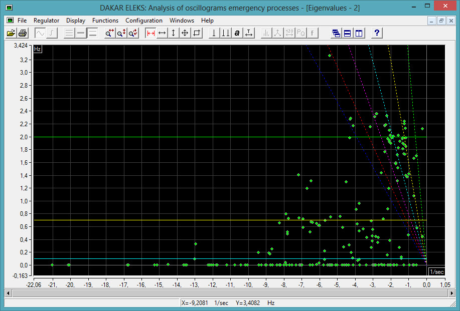
Figure 1 shows Ukraine’s power system states based on the modal method. As you can see, the power system states are separated in the damping zone by slope lines of different colours. To various extents, the position of each point is influenced by all power system generators with a different impact degree. Oscillation static stability of a power system is achieved when all system points are located on the left of cross axis. A power system is damped enough if all its states fall outside the 5% damping zone. If a power system state is within the 5% zone, this may cause mode oscillation and destroy oscillating static stability.
You can change power system states using generators parameters, which means changing power system stability as required. For example, let’s analyse the state with a real part of -0.214 and frequency of 0.44 Hz. Table 1 presents the results of modal analysis for state -0.214 and has the following notation: gen. name – generator name, pij – impact degree of generator i on the eigenvalue j formation. We show only the first nine generators which have the most impact on the formation studied state. The stability margin of the studied state is 0.214. Look at the generator TG-4 of Rivne NPP block No. 2. The impact of the generator TG-4 of Rivne NPP on the studied state is 19.9%.
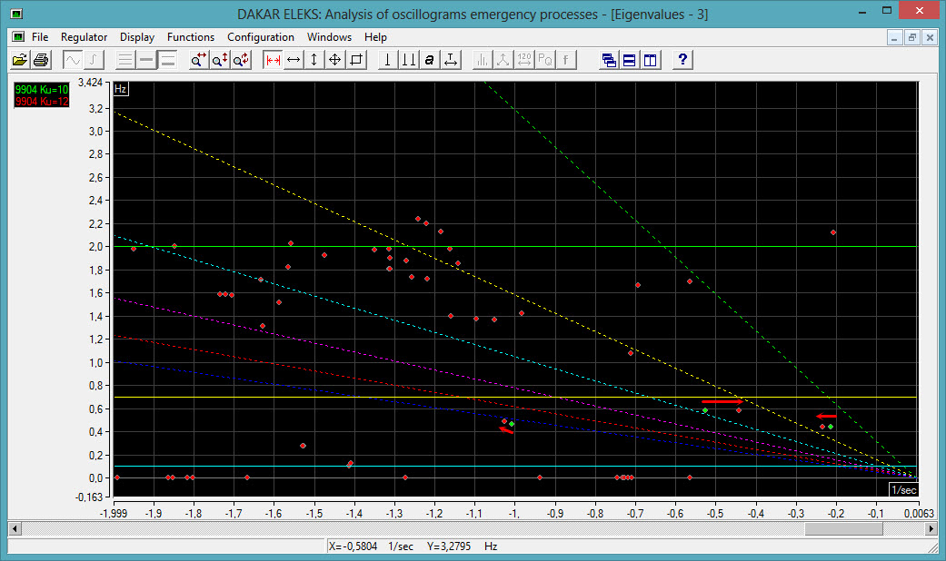
Now let’s investigate their moves by change generator parameters, for example the move of this state by changing the generator parameter from the value kU = 10 to kU = 12. We changed the initial value by 20%. Results show that the state stability margin of the studied state has increased by 8.9 % compared to the initial value and equals 0.233. Figure 2 shows the move of power system states by the change parameter generator. The studied generator influences not one state, but all states of a power system with a different degree.
Now, we’ll check the correctness of the generator impact on the formation of the studied state. To do this, let’s investigate the movement of the studied state by changing the generator’s parameter of Yuzhnoukrainsk PP block No. 3 from the value k′f = 2 to k′f = 3. We changed the initial value by 50%. In case k′f = 2, the impact of the generator of Yuzhnoukrainsk PP block No. 3 is 2.3%. After the generator’s parameter k′f is changed, the state stability margin is 0.218, meaning it is changed by 1.9 % compared to the initial value.
So, we can conclude that changing the generator parameter that has more impact on the studied state formulation causes more changes to the state stability margin. This verifies the correctness of our mathematical model. We obtained a powerful mechanism to control system parameters: by changing them, we can determine the optimal values of system parameters to ensure the largest stability margin for a certain state and the entire power system.
| gen. name | 9904_G: TG 4 RNPP |
9905_G: No.3 RNPP |
9906_G: No.4 RNPP |
9808_G: No.2 KhNPP |
9903:_G: TG 3 RNPP |
9315_G: No.5 ZNPP |
9314_G: No.4 ZNPP |
9313_G: No.3 ZNPP |
9599_G: No.3 YuPP |
|---|---|---|---|---|---|---|---|---|---|
| Pij | 0.199 | 0.159 | 0.158 | 0.075 | 0.031 | 0.024 | 0.024 | 0.024 | 0.023 |
Table 1. Generators impact degree on the studied state for the case parameter kU = 10 of the generator
Conclusion
Selective modal analysis is a very powerful method for management and operation of complex systems. It can be used not only for power systems, but also for systems that have small oscillations. For example, we can apply it to solving macro- and microeconomics problems, image processing and much more. Contact our team to learn more.
Related Insights


The breadth of knowledge and understanding that ELEKS has within its walls allows us to leverage that expertise to make superior deliverables for our customers. When you work with ELEKS, you are working with the top 1% of the aptitude and engineering excellence of the whole country.

Right from the start, we really liked ELEKS’ commitment and engagement. They came to us with their best people to try to understand our context, our business idea, and developed the first prototype with us. They were very professional and very customer oriented. I think, without ELEKS it probably would not have been possible to have such a successful product in such a short period of time.

ELEKS has been involved in the development of a number of our consumer-facing websites and mobile applications that allow our customers to easily track their shipments, get the information they need as well as stay in touch with us. We’ve appreciated the level of ELEKS’ expertise, responsiveness and attention to details.


